The Training Reactor of the Budapest University of Technology and Economics is a light water moderated and cooled reactor of 100 kW nominal thermal power (Fig. 1). The core consists of EK-10 type fuel assemblies, containing 10% enriched UO2 in metal magnesium matrix. The fuel region is surrounded by graphite reflector assemblies. The maximum thermal neutron flux in the reactor core is 2.7·1012n/cm2s.
The main purpose of the facility is the training of young engineers and physicists. On the other hand, research projects are also carried out on the reactor and using the connected experimental devices. The reactor can also be used for the production of short-lived radioisotopes. Neutron and gamma irradiations can be performed using the vertical irradiation channels, horizontal beam tubes, the large irradiation tunnel and the pneumatic rabbit systems. Radiochemical laboratories and a hot cell support the training and research activities.
The facility was designed by Hungarian engineers and physicists in the 1960’s. For the design process, the experience gained during the operation of several critical assemblies, and the then 2 MW Budapest Research Reactor (originally designed by Soviet engineers), was effectively applied. The core first went critical in the summer of 1969 as a critical assembly at the BRR site, commissioning at its current location was in May 1971.

The reactor is located at the Central Campus of BME. The reactor core is at the bottom of an aluminum tank of 140 cm diameter and approximately 600 cm height, with a wall thickness of 20 mm. The open vessel, which is filled with demineralized water, is surrounded by a concrete (ordinary + heavy) bioshield of 2 m thickness. In vertical direction above the reactor core, the shielding is ensured by the approximately 5 m thick water layer. As the vessel is open on the top, easy access is provided to the core. A vertical section of the tank and the bioshield is shown in Fig. 2. One of the five horizontal beam ports with the inner guide tubes is also shown in this figure. All but one of the ports have a diameter of 90 mm, while one has a diameter of 110 mm. All five horizontal beam guides and their layout with reference to the core is shown in Fig. 3.


Fig 4. shows the large irradiation tunnel, which is actually a cavity in the bioshield, being normally filled with large pieces of reactor purity graphite to provide a thermal column. The external area of the tunnel is 1.3 x 1.7 m2, gradually narrowing towards the reactor core. The surface that is facing the core has an area of 0.5 x 0.64 m2, simultaneously being the outer surface of the aluminum reactor vessel (flattened in that region). The purpose of the tunnel is manyfold: for most experiments it is used as a thermal column, while it can also be applied to irradiate larger devices. A remote operated trolley facilitates replacing of the graphite with other devices/material to irradiate. Three vertical irradiation tubes are also connected to the tunnel.

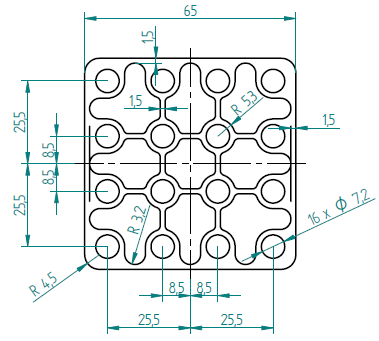
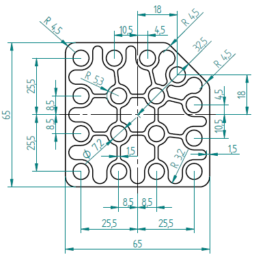
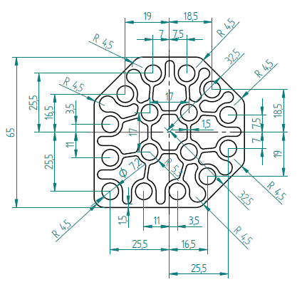
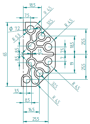
The fuel, which was made in the 1960’s in the former Soviet Union, has a total mass of 29.54 kg. The dimensions of the fuel element and bundle are depicted in Figs. 5 and 6, respectively. As shown in Fig. 6, there are four different types of assemblies, which differ in the arrangement of the fuel pins. The pin pitch in the regular assemblies is 17 mm. Each fuel pin contains nominally 80 g uranium with the corresponding amount of oxigen and 13 g metal magnesium. The active length is 500 mm. The cladding of the fuel pin is 99.5% purity aluminum alloy, with an outer diameter and thickness of 10 mm and 1.5 mm, respectively. At each end of the fuel pins, there are inactive parts with a length of 45 mm.


The current core of the reactor contains a total of 24 fuel assemblies, which together contain 369 fuel pins (Fig. 7). The core also contains 41 solid graphite blocks with aluminum cladding and a holder element, which serve as the reflector around the core. Some of the graphite blocks are penetrated by aluminum elements in the cut of the horizontal beam tubes to increase the beam intensity. In the corner assemblies, graphite blocks are cut diagonally, the remaining space being filled by air.
The size of the fuel and graphite assemblies are 68 mm x 68 mm x 600 mm (excluding the bottom skirt and the top knob parts). The thickness of the graphite assembly cladding is 1.5 mm, while the thickness of the fuel assembly cladding is 1.2 mm. The gap between two adjacent assemblies is 4 mm. The size of the core is 578 mm x 650 mm x 600 mm (excluding the holder elements from the height).
Fig. 7 shows the layout of the fuel and graphite assemblies, as well as the positions of control and safety rods, the starting neutron source, the pneumatic rabbit system and the vertical irradiation channels (unmarked, water-filled tubes). Fig. 8 shows a 3D view of the core.


Four, electromagnetically suspended control and safety rods ensure the reactivity control and the safe shutdown of the reactor. The rods are inserted into aluminum guiding tubes with 30~mm diameter and 1.5~mm thickness. A remote operated AmBe neutron source is used to provide the starting neutrons for the first startup on a given operational day. There are two types of absorber rods. In the case of the safety rods, the guiding tubes are filled with air, while the guiding tubes of the control rods are filled with water. According to the available information, in case of the two safety rods and the manual control rod, the absorbent material is B4C, while the automatic control rod is a cadmium covered aluminum tube. The active length of all control rods is 600 mm. The bottom levels of the absorbents are 73 mm below the bottom level of the fuel. The monitoring instrumentation of the reactor core, ie. the neutron detectors, are located in protecting tubes around the core. In the startup range, two fission chambers ensure the information on the neutron flux levels. In the power range, boron lined ionization chambers provide the level and period protection. The power is measured using a calibrated ionization chamber. There are also temperature measurements in the primary coolant circuit of the reactor. A thermocouple is located at core exit, another one in the upper region closer to the water surface, while the inlet and outlet temperatures of the reactor tank are also measured. The temperatures must be between 20 and 60 °C, otherwise the core can be cooled with natural circulation even on nominal power. The moderator can be heated by an electrical heater tank and cooled by a heat exchanger connected to the primary circuit. The fuel has not been replaced since the startup of the reactor (1971). The average burnup of the fuel can be calculated from the integrated released energy, which is approximately 400 MWdays. This corresponds to a burnup level of 0.7 MWdays/kg. The maximum excess reactivity of the core is about 65 cents, while the minimum allowed reactor period is 10 s.

